UV DTF printer heads aligned calibration steps video
Print the job file and check the color、white、varnish、and glue alignment
As seen in the printed effect from the above video, the color and white/varnish/glue are not aligned. It needs to be calibrated, go to the print software "Calibration" menu and refer to the following steps:
Please check the nozzle test first,refer to the following video:
Step 1:
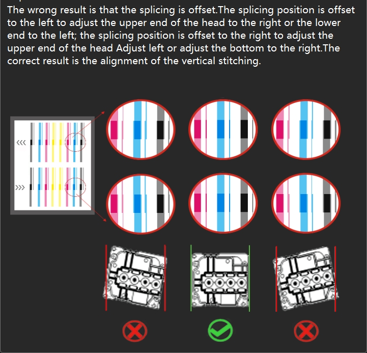
Print the calibration chart line of "Head Install - Vertical Check", check whether the print head is installed vertically, and manually adjust the vertical Angle of the print head.
Please refer to the following video 1 :
Please refer to the following video 2 :
Step 2:
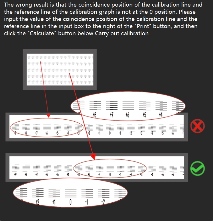
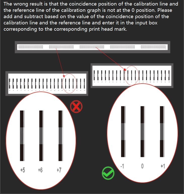
Print the calibration chart line of "Step Adjust - Base Step" and check that the base step calibration line is aligned at position 0. If the calibration line is actually aligned at +1, enter "+1" in the pixel box, then click "Calculate", then click "Save" in the upper right corner to save the calibration parameters. If the calibration line is actually aligned at -1, enter "-1" in the pixel box, then click "Calculate", then click "Save" in the upper right corner to save the calibration parameters. Modify the values and print the calibration chart again to see if the 0 position of the calibration line is aligned.
(At the same time check all the pass values in the step offset, change the step offset value of each pass to 0, and then save)
Please refer to the following video :
Step 3:
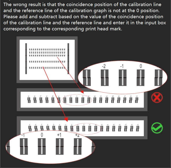
Print the calibration chart line of "Head space - Horizontal - Left distance" and check that all H2-H3-H4 calibration chart lines are aligned at position 0.
First check the calibration chart corresponding to H2. If the calibration line is actually aligned at +1, add 1 to the original value in H2 box, and then click "Save" in the upper right corner to save the calibration parameters. If the calibration line is actually aligned at -1, minus 1 from the original value in the H2 box and click "Save" in the upper right corner to save the calibration parameters.
Then check the calibration chart corresponding to H3. If the calibration line is actually aligned at +1, add 1 to the original value in H3 box, and then click "Save" in the upper right corner to save the calibration parameters. If the calibration line is actually aligned at -1, minus 1 from the original value in the H3 box and click "Save" in the upper right corner to save the calibration parameters.
Finally, check the calibration chart corresponding to H4. If the calibration line is actually aligned at +1, add 1 to the original value in H4 box, and then click "Save" in the upper right corner to save the calibration parameters. If the calibration line is actually aligned at -1, minus 1 from the original value in the H4 box and click "Save" in the upper right corner to save the calibration parameters.
Modify the values and print the calibration chart again to see if the 0 position of the calibration line is aligned.
Please refer to the following video :
Step 4:
Print the calibration chart line of "Head space - Horizontal - Right distance" and check that all H2-H3-H4 calibration chart lines are aligned at position 0.
First check the calibration chart corresponding to H2. If the calibration line is actually aligned at +1, add 1 to the original value in H2 box, and then click "Save" in the upper right corner to save the calibration parameters. If the calibration line is actually aligned at -1, minus 1 from the original value in the H2 box and click "Save" in the upper right corner to save the calibration parameters.
Then check the calibration chart corresponding to H3. If the calibration line is actually aligned at +1, add 1 to the original value in H3 box, and then click "Save" in the upper right corner to save the calibration parameters. If the calibration line is actually aligned at -1, minus 1 from the original value in the H3 box and click "Save" in the upper right corner to save the calibration parameters.
Finally, check the calibration chart corresponding to H4. If the calibration line is actually aligned at +1, add 1 to the original value in H4 box, and then click "Save" in the upper right corner to save the calibration parameters. If the calibration line is actually aligned at -1, minus 1 from the original value in the H4 box and click "Save" in the upper right corner to save the calibration parameters.
Modify the values and print the calibration chart again to see if the 0 position of the calibration line is aligned.
Please refer to the following video :

Step 5:
Print the calibration chart line of "Head space - Vertical distance" and check that all H2-H3-H4 calibration chart lines are aligned at position 0.
First check the calibration chart corresponding to H2. If the calibration line is actually aligned at +1, add 1 to the original value in H2 box, and then click "Save" in the upper right corner to save the calibration parameters. If the calibration line is actually aligned at -1, minus 1 from the original value in the H2 box and click "Save" in the upper right corner to save the calibration parameters.
Then check the calibration chart corresponding to H3. If the calibration line is actually aligned at +1, add 1 to the original value in H3 box, and then click "Save" in the upper right corner to save the calibration parameters. If the calibration line is actually aligned at -1, minus 1 from the original value in the H3 box and click "Save" in the upper right corner to save the calibration parameters.
Finally, check the calibration chart corresponding to H4. If the calibration line is actually aligned at +1, add 1 to the original value in H4 box, and then click "Save" in the upper right corner to save the calibration parameters. If the calibration line is actually aligned at -1, minus 1 from the original value in the H4 box and click "Save" in the upper right corner to save the calibration parameters.
Modify the values and print the calibration chart again to see if the 0 position of the calibration line is aligned.
Please refer to the following video 1 :
Please refer to the following video 2 :
Step6:
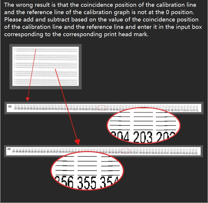
Print the calibration chart line of "Bidirec Adjust" and check that the calibration chart line is aligned at position 0. If the calibration line is actually aligned at +1, add 1 to the original value in the Bidirect Value box and click "Save" in the upper right corner to save the calibration parameters. If the calibration line is actually aligned at -1, minus 1 from the original value in the Bidirect Value box and click "Save" in the upper right corner to save the calibration parameters. Modify the values and print the calibration chart again to see if the 0 position of the calibration line is aligned.
Please refer to the following video :
After all the above steps are completed, the calibration is complete, and the job file is printed again to check the final print effect. If the above calibration is completed, the lines are aligned, but the actual print job file, the pattern is still not aligned, it is recommended to repeat the above steps once. If it is the same, it is necessary to rule out whether the print head nozzle is abnormal, check the status of the print head nozzle, whether there is a deficiency or abnormal flying ink, if so, soak and clean the print head to see whether it is improved.
Download link for HD version of the above video:
Add: No.6-2, Jinhua Zhong Road,Zhongshan
Tel: 86-760-88667090
Fax: 86-760-88667096
E-mail: betty@titanjet.com.cn
vivian@titanjet.com.cn
market2@titanjet.com.cn
market3@titanjet.com.cn